Electric Field
Electric Charges
Electric charges result from the flow of electrons from a charged body to an uncharged body.
Types of Charges
- Positive charge
- Negative charge
Production of Electric Charges
Electric charges can be generated using the following methods:
- Friction
- Induction
- Contact
1. Charging by Friction
When an uncharged polythene rod is rubbed with fur, electrons transfer from the fur to the polythene rod, making the polythene negatively charged.
Similarly, when an uncharged glass rod is rubbed with silk, electrons move from the glass rod to the silk, causing the glass rod to become positively charged.
2. Charging by Induction
In this method, an electric charge is produced by bringing a charged body near an uncharged body. The process involves the following steps:
- Bringing a positively charged object close to an insulated body.
- Momentarily touching the insulated body to allow excess charge to conduct away (earthing).
- Removing the inducing charge, leaving the body with an opposite charge.
3. Charging by Contact
In this method, a charged object is brought into direct contact with a neutral object. The neutral object acquires the same charge as the charged object. For example, if a positively charged glass rod is placed near a neutral insulated body, the body will gain a positive charge.
Conductors
Conductors are materials that allow electrons to pass through them easily, enabling them to conduct electricity. Examples include:
- Metals
- Graphite
- Acids
- Salt solutions
- The Earth
- The human body
Insulators
Insulators are materials that do not allow electrons to pass through them easily. Examples include:
- Plastic
- Polythene
- Paper
- Ebonite
- Dry hair
- Silk
- Glass
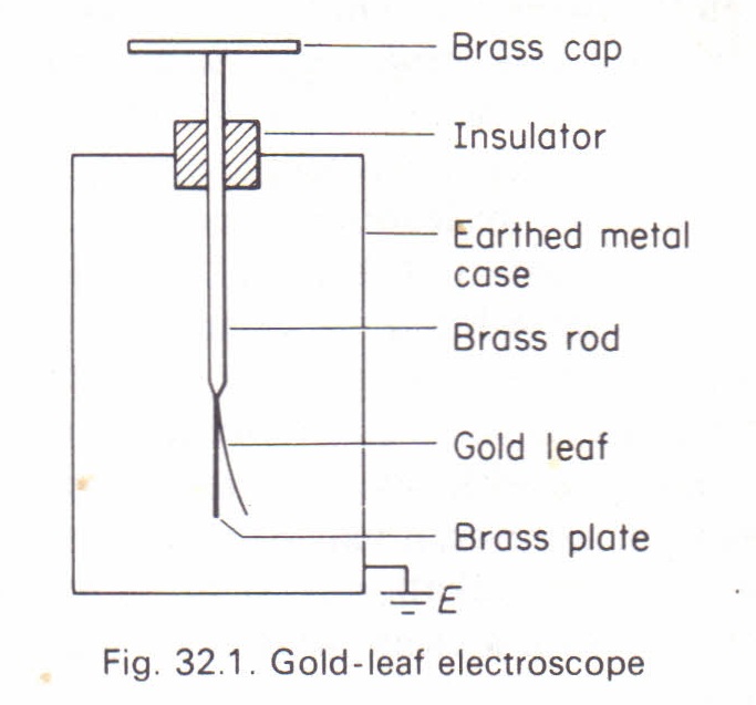
Electroscope
An electroscope is an instrument used for detecting and testing small electric charges. It consists of a metal (brass) rod attached to a thin gold or aluminum leaf. The rod is fitted with a brass cap or disc and is insulated from the metal case.
A gold-leaf electroscope can be charged using the induction method. If a positively charged rod is brought near a positively charged electroscope, the leaf divergence increases. If an oppositely charged object is brought near, the divergence decreases.
 Credit: physicsmax
An electric field is a region of space surrounding a system of electric charges where electrical forces act on any charge placed within the region. The electric field is a vector quantity, and its direction can be determined using a test charge (a small positive charge).
Fundamental Law of Electrostatics
The fundamental law of electrostatics states that:
"Like charges repel, unlike charges attract."
Coulomb’s Law of Electrostatic Force
Coulomb’s law states that the electrostatic force of attraction or repulsion (\( F_C \)) between two point charges is directly proportional to the product of the charges and inversely proportional to the square of their separation.
Mathematically,
\[ F_C \propto \frac{Q_1 Q_2}{r^2} \]
Introducing a constant \( k \):
\[ F_C = k \frac{Q_1 Q_2}{r^2} \]
Where:
- \( k = \frac{1}{4 \pi \epsilon_0} \)
- \( \epsilon_0 = 8.85 \times 10^{-12} \text{ F/m} \)
- \( k = 9 \times 10^9 \text{ Nm}^2/\text{C}^2 \)
Electric Field Intensity or Strength (\(E\))
Electric field intensity is defined as the electric force per unit charge. It is a vector quantity and is expressed in \( \text{N/C} \).
\[ E = \frac{F_C}{Q} \]
Substituting \( F_C \):
\[ E = \frac{Q}{4 \pi \epsilon_0 r^2} \]
Electric Potential (\( V_E \))
Electric potential at a point in an electric field is defined as the work done in bringing a unit charge from infinity to that point. It is a scalar quantity and is measured in volts.
\[ V_E = E r \]
Substituting \( E \):
\[ V_E = \frac{Q}{4 \pi \epsilon_0 r} \]
Conductors and Their Properties
A conductor may possess one or more of the following properties:
- It may act as a resistor, meaning it primarily converts electrical energy into heat when current flows through it.
- It may act as a capacitor, meaning it stores electrical energy or charge when a current passes through it.
- It may act as an inductor, meaning it stores magnetic energy when a current passes through it.
Capacitors
A capacitor is a device used to store electrical energy or charge. Most capacitors consist of two conductors separated by an insulating material (dielectric). The most common type is the parallel plate capacitor.
Charging a Capacitor
When a capacitor is connected across a voltage source, opposite charges gradually accumulate on each plate. The charge on one plate is \( +Q \), while the charge on the other is \( -Q \). The dielectric material between the plates acts as an insulator.
Capacitance
The capacitance (\( C \)) of a capacitor is the ratio of the charge stored (\( Q \)) to the potential difference (\( V \)) between the plates.
\[ C = \frac{Q}{V} \]
The unit of capacitance is the farad (F).
Factors Affecting the Capacitance of a Parallel Plate Capacitor
1. Area of Overlap (\( A \)): The capacitance is directly proportional to the area of the plates.
\[ C \propto A \]
2. Distance Between the Plates (\( d \)): The capacitance is inversely proportional to the separation between the plates.
\[ C \propto \frac{1}{d} \]
3. Dielectric Constant (\( \epsilon \)): The capacitance is directly proportional to the permittivity (\( \epsilon \)) of the dielectric material.
\[ C \propto \epsilon \]
Summarily, the capacitance of a parallel plate capacitor is given by:
\[ C = \frac{\epsilon A}{d} \]
where:
- A = Area of the plates
- d = Distance between the plates
- \( \epsilon \) = Permittivity of the dielectric medium (F/m)
Energy Stored in a Capacitor
A capacitor stores electrical energy. When it is connected to a potential difference (p.d.) source, the charge on its plates gradually builds up from zero to \( Q \). The work done in charging the capacitor is given by:
\[ W = \frac{1}{2} QV \]
Also, using the relation \( Q = CV \), we can express the energy stored as:
\[ W = \frac{1}{2} C V^2 \]
or
\[ W = \frac{1}{2} \frac{Q^2}{C} \]
Example
A capacitor with a capacitance of 3.0 \( \mu \)F is connected across a potential difference of 2000 V. Calculate the energy stored in the capacitor.
Given:
- Capacitance, \( C = 3.0 \times 10^{-6} \, F \)
- Potential difference, \( V = 2000 \, V \)
- Energy stored, \( E = ? \)
Recall the energy stored in a capacitor is given by:
\[ E = \frac{1}{2} C V^2 \]
Substituting the values:
\[ E = \frac{1}{2} \times (3.0 \times 10^{-6}) \times (2000)^2 \]
\[ E = \frac{1}{2} \times (3.0 \times 10^{-6}) \times 4000000 \]
\[ E = 6.0 \times 10^{-6} \times 10^6 \]
\[ E = 54 J \]
Thus, the energy stored in the capacitor is 54 J.
Arrangement of Capacitors
Capacitors can be arranged in a circuit either in parallel or in series.
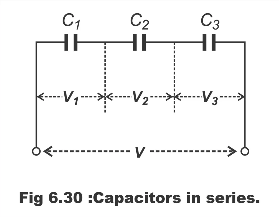
Series Arrangement
 Credit: electroniclinic
- Equal charge \( Q \) is stored in each capacitor: \( Q_1 = Q_2 = Q_3 \).
- The sum of the potential differences across each capacitor equals the total supplied voltage:
\[ V = V_1 + V_2 + V_3 \]
Since \( C = \frac{Q}{V} \), we substitute for \( V \):
\[ \frac{Q}{C} = \frac{Q}{C_1} + \frac{Q}{C_2} + \frac{Q}{C_3} \]
Canceling \( Q \), we get:
\[ \frac{1}{C_{\text{eq}}} = \frac{1}{C_1} + \frac{1}{C_2} + \frac{1}{C_3} \]
This means the reciprocal of the equivalent capacitance for capacitors in series is equal to the sum of the reciprocals of the individual capacitors.
Parallel Arrangement
- The potential difference across each capacitor is the same: \( V = V_1 = V_2 = V_3 \).
- The total charge stored is the sum of the charges stored in each capacitor:
\[ Q = Q_1 + Q_2 + Q_3 \]
Since \( Q = CV \), we substitute:
\[ C V = C_1 V + C_2 V + C_3 V \]
Canceling \( V \), we get:
\[ C_{\text{eq}} = C_1 + C_2 + C_3 \]
Thus, for capacitors in parallel, the total capacitance is the sum of the individual capacitances.